Drawing & File Support for CNC Machining
Precision manufacturing relies on the accuracy of technical data. High-quality CAD files for CNC machining and clean 2D prints streamline our DFM review, eliminate quoting ambiguities, and accelerate cycle time from file intake to first-article inspection.
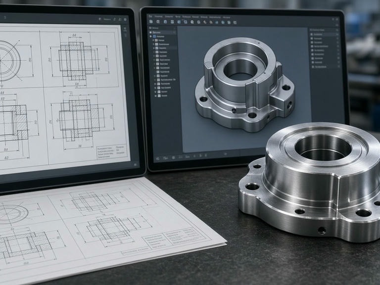
Complete CAD datasets with annotated GD&T ensure accurate toolpath programming and rapid cycle times across our multi-axis fleet.
The Role of Documentation in CNC Machining
PRECI5 processes projects ranging from complex 5-axis prototypes to high-volume production. To provide a precise quote, our engineering team must evaluate the geometry, material requirements, and critical tolerances defined in your files.
Incomplete data often leads to back-and-forth communication, which delays project initiation. Providing a complete data package—including both 3D models and 2D drawings—ensures that our manufacturing process planning aligns with your design intent from day one.
How Technical Data Impacts Cost & Lead Time
Engineering review is the initial checkpoint in our production workflow. Clearly defined tolerances and material designations let our estimators define the most cost-effective machine routing immediately.
Tightly toleranced geometric features route directly to high-precision 5-axis work centers, while symmetric shafts map to multi-axis turn-mill cells to curb fixture setups. Thorough documentation minimizes scrap, improves tool life, and shortens cycle times.
Accepted File Formats
Our CAM programming suites integrate seamlessly with neutral CAD formats and detailed technical vectors. Final software compatibility is confirmed against live production stations.
3D Models (Toolpath Programming)
CAM PrimarySTEP file CNC machining is preferred because STEP (.stp, .step) standardizes surface boundaries cleanly across differing CAD kernels. We also accept IGES (.igs, .iges) and Parasolid (.x_t) files.
- • STEP (.stp, .step): Preferred for cross-platform geometric integrity
- • IGES (.igs, .iges): Surface definition fallback
- • Parasolid (.x_t): Recommended for Parasolid-based CAD assemblies
2D Technical Drawings (Inspection & GD&T)
QA PrimaryClear 2D drawings are indispensable for CNC machining drawing requirements. A fully dimensioned PDF remains our master legal reference for inspection, datum schemes, threaded holes, and surface calls.
- • PDF (.pdf): Primary standard with title block, tolerances, and notes
- • DWG / DXF (.dwg, .dxf): Accepted reference files for profiles & sheet layouts
RFQ Information Table
Review your package against this checklist before submitting a CNC machining RFQ. Supplying these parameters upfront allows us to generate formal quotes within 24 to 48 hours.
| Required Information | Description & Engineering Significance | Standard Deliverable Example |
|---|---|---|
| 3D Model | Neutral geometry source used directly for toolpath calculation and roughing operations. | .STP / .STEP / .X_T file |
| 2D Drawing | Master document defining datums, non-modeled threads, and inspection notes. | Vector-based PDF with title block |
| Material & Grade | Full alloy composition, temper designation, or commercial trade grade for raw stock procurement. | Al 6061-T6, SS316L, PEEK, Ti-6Al-4V |
| Quantity | Total volume and prototype vs. recurring production tier splits to model batch setups. | 10 pcs prototype / 250 pcs batch |
| Critical Tolerances / GD&T | Tight limits, true position, perpendicularity, parallelism, and associated datum references. | ±0.01 mm, True Position Ø0.02 | A | B | C |
| Surface Finish | Roughness average (Ra) targets and subsequent post-processing requirements. | Ra 0.8 μm, Type II Black Anodize, Bead Blast |
| Heat Treatment | Thermal stabilization, case hardening, or required core hardness benchmarks. | HRC 48–52, Stress Relieved, Solution Treated |
| Inspection Requirements | Verification scope required prior to shipment and customer acceptance criteria. | Full CMM report, FAI (AS9102), Raw Material Mill Certs |
| Required Delivery Date | Target receipt date to align shop loading, tooling orders, and freight logistics. | Standard (10-15 business days) / Expedited |
Our Manufacturing Infrastructure
PRECI5 operates a comprehensive facility in Shenzhen, designed to handle diverse manufacturing requirements from rapid prototyping to volume production. Our capacity is built on high-end Japanese machinery across 114 machining and supporting units.
Max travel: 900 × 900 × 700 mm; 24,000 rpm spindle for complex multi-sided parts.
Mazak VCN-430AL vertical machining centers built for stable serial production.
10× Mazak QTC100MY turn-mill units and 12× Mazak QTE100 CNC lathes.
2× Mazak HCN5000 horizontals plus 18× FANUC high-speed vertical centers.
Precision and Complex Geometry Capability
Our multi-axis footprint allows complex geometry components to be cut in a single setup, eliminating cumulative datum stacking across operations. Core machinery maintains a listed machine precision of 0.003 mm. Internal metrology is anchored by ZEISS coordinate measuring machines (CMM), optical comparators, roughness profilers, and calibrated hardness testers to verify full conformance to your CAD files.
Frequently Asked Questions
Quick technical references regarding file prep, geometric conversion, and RFQ submission.
Submit Your Files for Quote
Ready to begin your project? Upload or send your complete CAD dataset. Our engineering estimators provide thorough DFM feedback and formal quotations within 24 to 48 hours.
Recommended Archive: Please compress multiple parts and matching 2D prints into a single .ZIP or .7Z archive.
Direct Inquiries: info@5-axiscncmachining.com
Plant Location: