DFM Analysis for CNC Machining: Optimize Precision Parts for Production
Bridge the critical gap between conceptual CAD design and cost-efficient serial production. At PRECI5, our manufacturing engineers analyze your part geometry, fixturing orientation, and GD&T against dedicated Mazak 5-axis and high-speed CNC fleet capacities to eliminate costly tool wear, chatter, and excess setups before metal is cut.
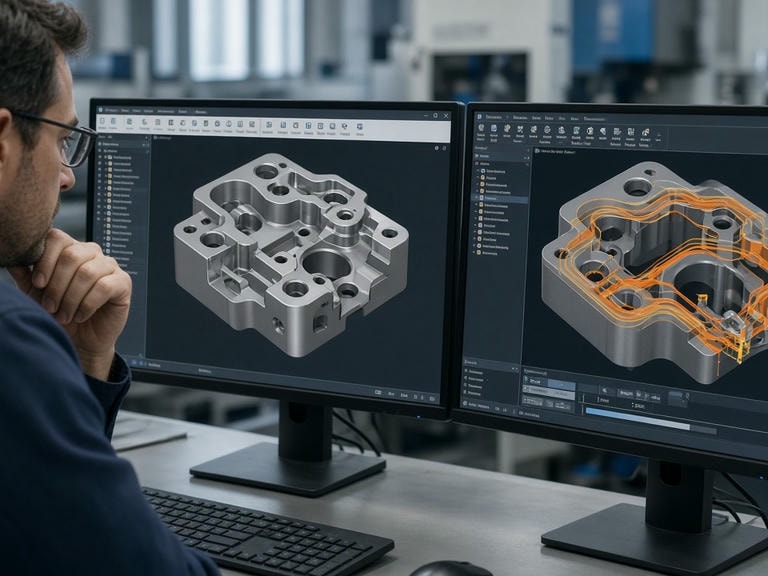
Engineering Feasibility
Why DFM Analysis is Critical for CNC Projects
For complex components, the difference between an expensive prototype cycle and a predictable production program hinges on proactive geometry optimization.
Setup & Datum Consolidation
Through continuous 5-axis kinematic evaluation, we reorient geometries to machine multi-sided features in a single clamping. This minimizes stack-up error and slash non-cutting handling time.
Tool Reach & Internal Radii
Deep pockets and sharp corners demand non-standard cutter lengths, driving up vibration. We recommend standard tool radii and corner tapers to maintain tool rigidity and lower tooling expenses.
Thin-Wall Deflection Mitigation
High-aspect thin walls flex under cutting pressures, causing chatter, geometric taper, and surface inconsistencies. Our analysis identifies minimum safe wall thicknesses across alloys and polymers.
Metrology & CMM Measurability
Every tolerance callout must be verifiable. We review datums and GD&T schemes to guarantee accessibility on our high-precision ZEISS coordinate measuring machines.
Production Muscle
DFM Grounded in Verified Fleet Specifications
Theoretical DFM often ignores real-world shop limits. At PRECI5, your design is validated directly against our operational capacity of over 50 precision CNC machines.
All DFM guidelines comply with certified AS9100D, IATF 16949, ISO 13485, ISO 9001, ISO 14001, and ISO 45001 manufacturing systems.
- Working Envelope: 900 × 900 × 700 mm
- Max Spindle: 24,000 RPM
- Application: Complex multi-axis contours
- Working Envelope: 560 × 430 × 510 mm
- Indexing: Integrated 4th axis rotary
- Application: High-volume repeatability
- Travel Limits: X 300 / Z 500 / Φ350 mm
- Live Tooling: Y-axis milling & turning
- Application: Concentric round features
Technical Matrix
DFM Checkpoints & Machine Limits
Compare common mechanical design features against PRECI5 machine capabilities to balance tight tolerances, tool rigidity, and production run costs.
| Design Feature | Engineering DFM Consideration | PRECI5 Machine Limit & Benchmark | Cost & Lead-Time Driver |
|---|---|---|---|
| 5-Axis Machining | Minimize multiple fixturing operations; evaluate rotary table clearance | Mazak C600: 900 × 900 × 700 mm (8 machines) | Eliminates soft-jaw development; protects datum relationships |
| 4-Axis Milling | Continuous cylindrical or angular indexing on orthogonal faces | Mazak VCN-430AL: 560 × 430 × 510 mm (39 machines) | Ideal for mid-to-high volume bracketry with 25-40% lower setup cost |
| Turn-Mill Operations | Combined turning and off-center cross drilling/milling | Mazak QTC100MY: X 300 / Z 500 / Φ350 mm (10 machines) | Completes rotational parts in single cycle; eliminates lathe-to-mill transfers |
| Internal Radii | Radius size must allow clearance for standard endmills (R ≥ tool diameter / 2) | Standard cutters down to R 0.5 mm; custom micro-endmills available | Sharp square inside corners require EDM or micro-milling, tripling cycle time |
| Deep Cavities | Depth-to-width ratio ≤ 4:1 recommended to limit tool deflection and chatter | Max depth verified against toolholder clearance and neck reach | Cavities beyond 6:1 require progressive feed reductions and custom extension holders |
| Thin Walls | 0.8 mm minimum for aluminum; 1.5 mm minimum for engineered plastics | High-speed dynamic toolpaths reduce lateral cutting force | Overly thin walls generate vibration chatter and out-of-spec parallelism |
| Hole Drilling | Depth-to-diameter ratio up to 10:1 standard; blind holes need drill point allowance | Dedicated micro-hole drilling equipment down to Φ 0.2 mm | Flat-bottom blind holes require extra bottom-facing passes and cleanout cycles |
| Surface Finish (Ra) | Specify fine Ra only on sealing faces, bearing journals, and sliding surfaces | Ra 0.4 – 0.8 μm as-machined via 24,000 RPM high-speed finishing | Defaulting entire part to Ra 0.4 increases finishing cycle time by up to 150% |
| Machine Precision | Geometric true position and dimensional tolerance stack-up | 0.003 mm machine positioning accuracy with ZEISS CMM validation | Tolerances below ±0.005 mm require temperature-controlled rooms and 100% CMM logs |
Systematic Workflow
Our 4-Stage DFM Review Process
We do not generate automated, surface-level auto-quotes. Every DFM package is evaluated by senior CNC tooling engineers.
CAD & GD&T Audit
We inspect your 3D STEP/IGES model and 2D print for cutter access, excessive aspect ratios, thread depth, and missing datum references.
Machine Matching
We match geometry to the most economical machine platform—routing complex multi-sided housings to our Mazak C600 5-axis or prismatics to our 39-machine 4-axis line.
Engineering Redline
You receive a technical report with actionable marked-up changes: recommended fillet increases, wall thickness stabilization, and tolerance relaxation options.
Production Ramp
Once the design revision is approved, CAM programming and fixture build commence seamlessly, locking in short lead times from first-article to full batch runs.
Design Guidance
DFM Frequently Asked Questions
Upload STEP + 2D Drawing for DFM Review
Avoid expensive rework, machining scrap, and delayed launches. Submit your engineering design files to receive a detailed manufacturability review and competitive volume quotation from our technical team.
- • 3D CAD: Native STEP (.stp) or IGES (.igs) solid model
- • 2D Drawing: PDF with GD&T, critical fits, threads, and surface roughness
- • Specifications: Material grade (e.g. Al 6061-T6, SS 316L, PEEK) and estimated batch volumes
Request an Engineering DFM Review
Fill in project details below to route files directly to our CNC manufacturing engineering queue.