CNC Machining Size Capacity & Precision Machining Tolerance
Evaluate your part geometries against our validated multi-axis envelope. At PRECI5, our production centers provide travel up to 900 mm and machine positioning precision down to 0.003 mm, backed by comprehensive CMM metrology.
Production Envelope Snapshot
Certified to ISO 9001, IATF 16949, AS9100D, ISO 13485, ISO 14001, and ISO 45001.
Machining Envelope & Equipment Matrix
Our facility utilizes a diverse fleet of Japanese Mazak and FANUC machining centers. Matching part dimensions with our physical axis travel ensures optimal tool access, rigid workholding, and efficient cycle times.
| Equipment Type | Model | Axis Configuration | Machining Travel / Capacity | Suitability Focus |
|---|---|---|---|---|
| 5-Axis CNC | Mazak C600 | Simultaneous 5-Axis | 900 × 900 × 700 mm | Complex structural frames, aerospace housings & multi-faced contours |
| 4-Axis Milling | Mazak VCN-430AL | Vertical + Rotary | 560 × 430 × 510 mm | Radial indexing, cylinder bores, side-milled brackets |
| Horizontal Machining | Mazak HCN5000 | Horizontal 4-Axis | 560 × 430 × 510 mm | Deep cavity chips evacuation, multi-sided prismatic bodies |
| High-Speed Vertical | FANUC VMC | Vertical 3-Axis | 500 × 400 × 300 mm | Rapid-turn precision brackets, electronic enclosures & electrodes |
| Turn-Mill Center | Mazak QTC100MY | Turning + Y-Axis Milling | X 300 / Z 500 / Φ350 mm | Turned shafts with cross-holes, flats, and off-center keyways |
| CNC Lathe | Mazak QTE100 | 2-Axis Precision Turning | X 300 / Z 300 / Φ350 mm | High-repeatability concentric bushings, pins, and circular connectors |
5-Axis Machining Size & Multi-Surface Integrity
Our core milling capability centers on an active battery of eight Mazak C600 5-axis machining centers. By consolidating complex operations into a single continuous setup, we eradicate the stacked tolerance errors inherent to repeated fixture re-clamping.
- • True Positional Consistency: Eliminates datum-transfer inaccuracies across angled holes, compound faces, and undercut geometries.
- • Optimized Cutter Rigidity: Shorter tool extensions reduce deflection and chatter on deep pockets and thin walls.
- • Smooth Organic Contours: 5-axis simultaneous interpolation delivers smooth continuous surface finishes suitable for aerospace and medical housings.
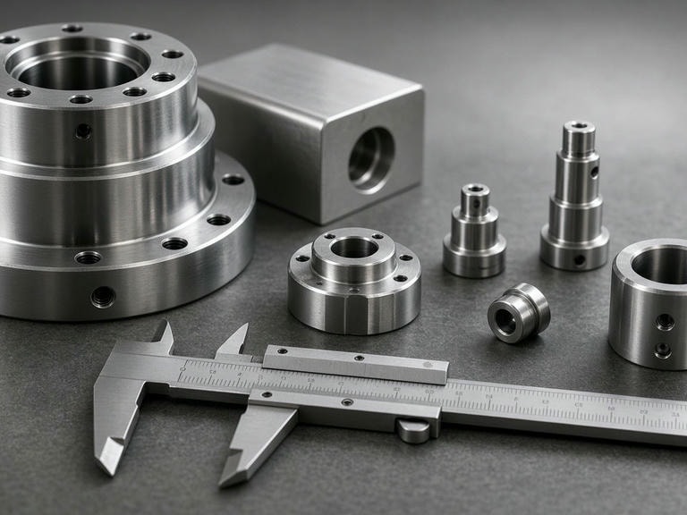
Multi-axis setup on Mazak C600, engineered for rigid structural components and tight positional GD&T callouts.
Machine Listed Precision vs. Finished Part Tolerances
Engineering honesty is the foundation of dependable manufacturing. While our machine tools boast ultra-precise positional ratings, final achievable part tolerances depend on real-world thermals, metallurgy, geometry, and metrology.
Machine Listed Base Precision
Manufacturer catalog positional specification under controlled factory test conditions:
Engineering Note: Machine accuracy represents encoder and ballscrew positional resolution. Finished part tolerances of ±0.003 mm cannot be universally guaranteed on all features or materials.
Key Drivers of Achievable CNC Tolerances
Explore the engineering variables we evaluate during technical review to calculate your true production tolerances:
Inspection-Driven Tolerance Verification
Validation is embedded into every stage of machining. Our temperature-controlled quality laboratory utilizes industry-standard coordinate measuring machines to ensure GD&T conformance on both prototype and serial production batches.
ZEISS CMM
Measuring volume: 700 × 700 × 600 mm for comprehensive 3D spatial reporting.
Sirius CMM
High-speed verification for serial part runs and batch repeatability checks.
Optical 2.5D Projector
Non-contact edge measurement for delicate micro-features and thin profiles.
Surface Profilometry
Precise Ra / Rz roughness inspection and calibrated hardness testing.
Standard Quality Certifications
Our quality management protocols operate under validated global industrial frameworks to serve aerospace, medical device, and automotive clients with complete traceability:
Full inspection documentation, including FAI (First Article Inspection), material certifications, and CMM dimensional logs, are available with every delivery.
Send Drawing for Tolerance Review
Upload your 2D prints (PDF, DWG) and 3D CAD files (STEP, IGES, X_T). Our application engineers will evaluate your dimensional callouts, suggest cost-effective machining envelopes, and provide a full DFM analysis within 24 hours.
Engineering Contact
STEP, STP, IGES, X_T, SLDPRT, PDF (with 2D GD&T)
DFM Review Checklist
- ✓ Machining travel and envelope compatibility
- ✓ Tolerance vs. material thermal stability
- ✓ Tool access & internal radius optimization
- ✓ Metrology setup & datum qualification